Tycon power sell a relatively cheap high power gigabit PoE injector. The high power bit means that it inserts power on all four ethernet pairs. This is important when using PoE to power devices over long cable lengths, especially if the devices draw a lot of current.
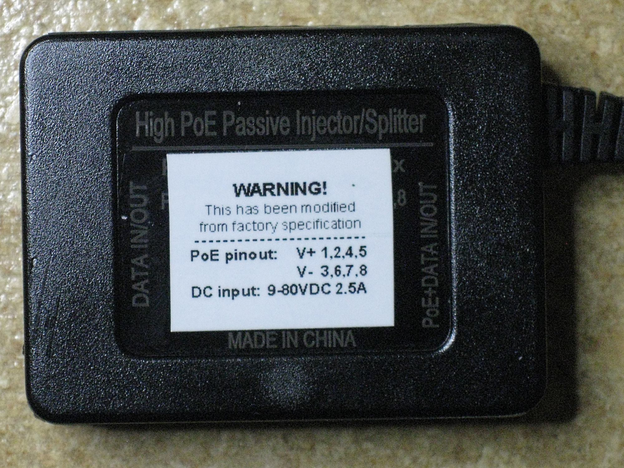
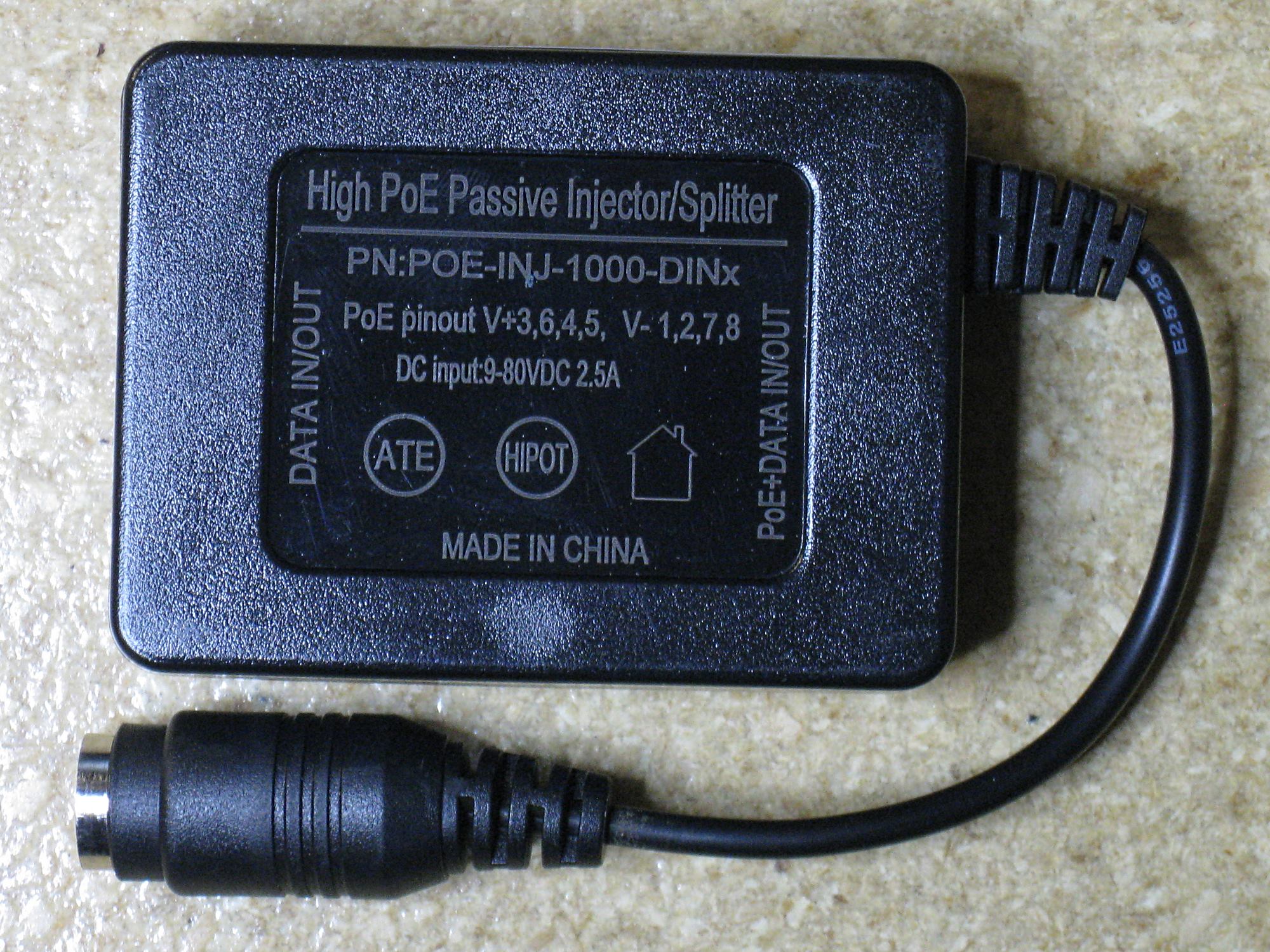
Tycon have two very similar models, the POE-INJ-1000-DIN and the POE-INJ-1000-DINx. The only difference between these models is the pinout for the PoE.
| Model | +ve pins | -ve pins |
| POE-INJ-1000-DIN | 1 2 4 5 | 3 6 7 8 |
| POE-INJ-1000-DINx | 1 2 7 8 | 3 4 5 6 |
As Murphy’s Law would have it, I need the POE-INJ-1000-DIN, but it doesn’t seem to be sold in Australia and New Zealand, however the POE-INJ-1000-DINx is available everywhere.
In the name of finding a quick and dirty solution, I decided to find out how easy it was to convert the DINx model to work like a “non x”. The first job was to work out exactly what needed changing. Ethernet pairs are 1-2, 3-6, 4-5 and 7-8.
| Model | pins 1 & 2 | pins 3 & 6 | pins 4 & 5 | pins 7 & 8 |
| POE-INJ-1000-DIN | + | _ | + | – |
| POE-INJ-1000-DINx | – | + | + | – |
As per the table above, we only need to swap the first two pairs. The other two stay as-is.
It turns out it only requires cutting PCB traces in two locations and adding two solder bridges to perform the conversion. The steps are detailed below.
Firstly, say goodbye to your warranty…..
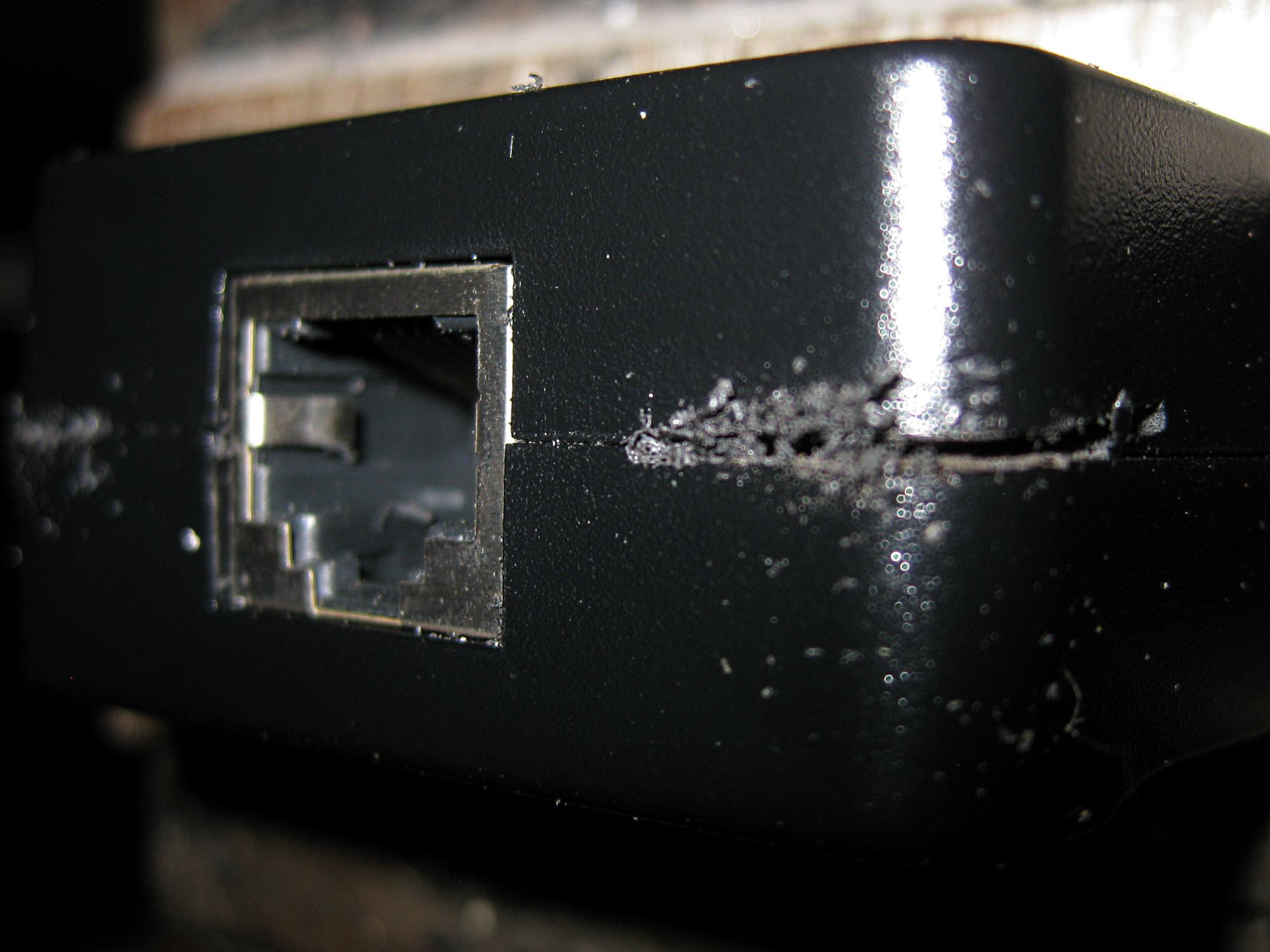
The two halves of the case are joined together very tightly. I suggest using a hacksaw on one corner to create a slot that can be levered open with a screwdriver. You can then work your way around until you have the case in two pieces.
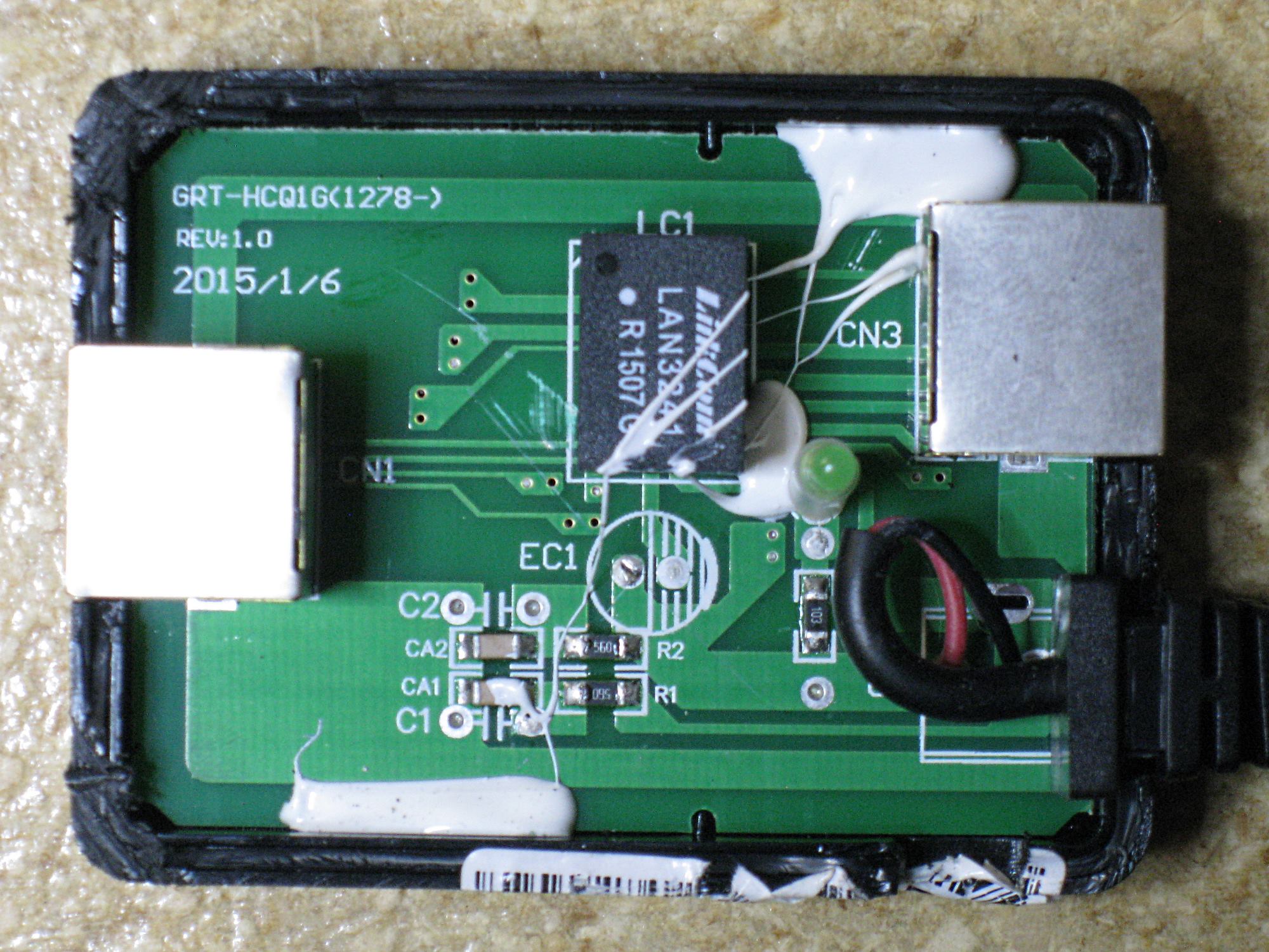
Remove the glue around the edges of the PCB and it should slip out of the case.
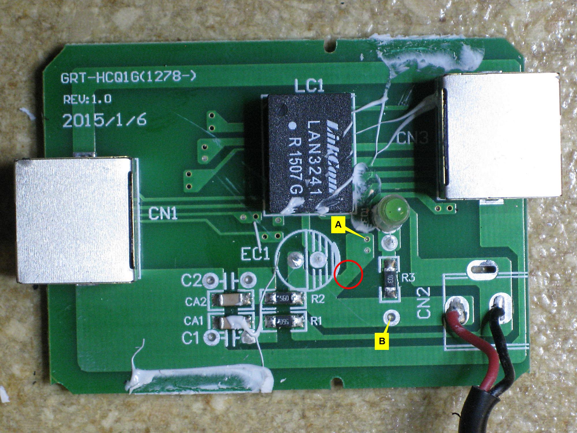
The PoE injector transformer is a Link Com LAN3241 – (Datasheet).
Take a sharp (hardened steel is helpful) blade and cut the trace at the location circled in red. You can check you’ve cut right through with a multimeter on continuity test between points A and B.
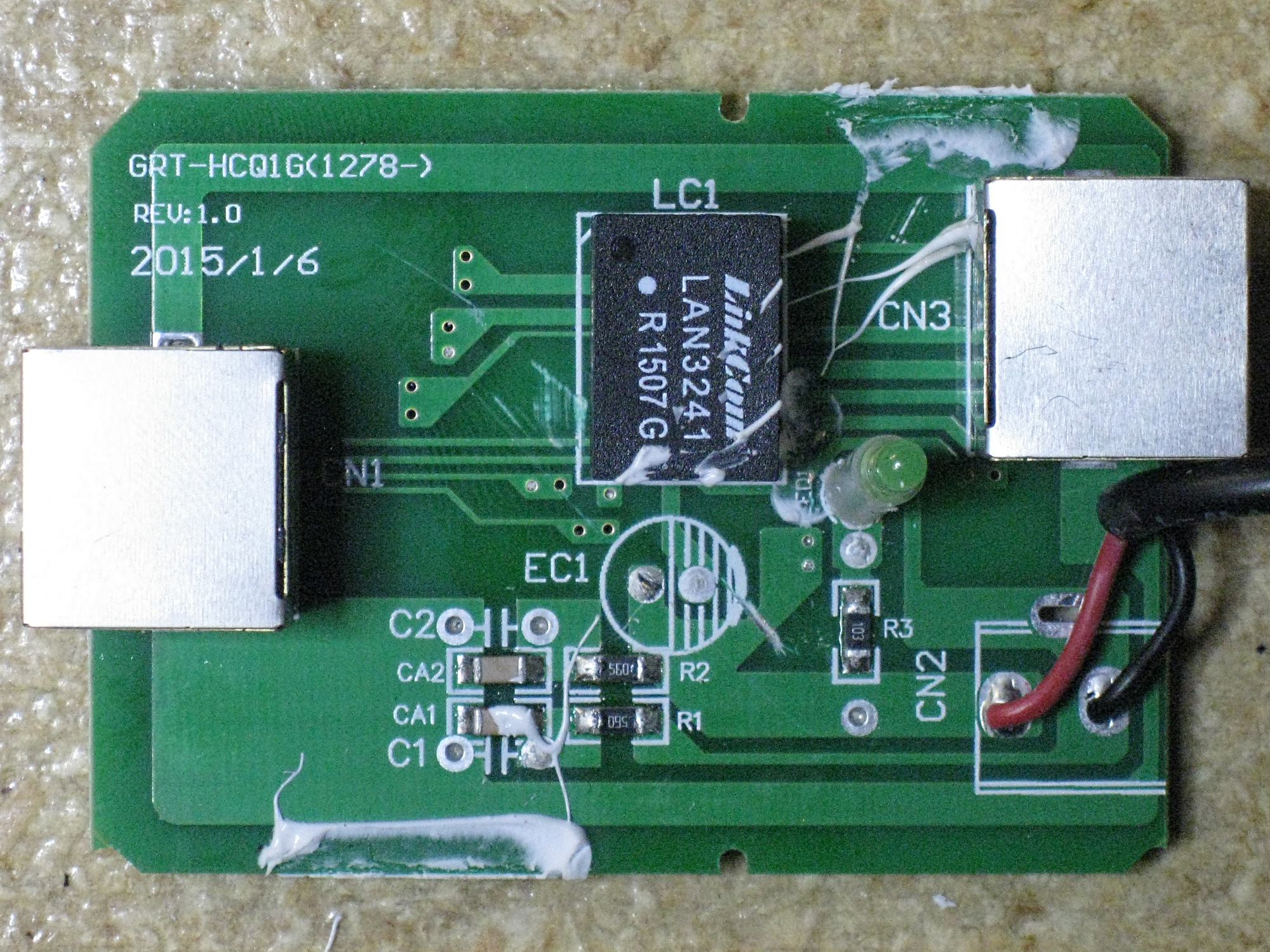
The board should now look like this.
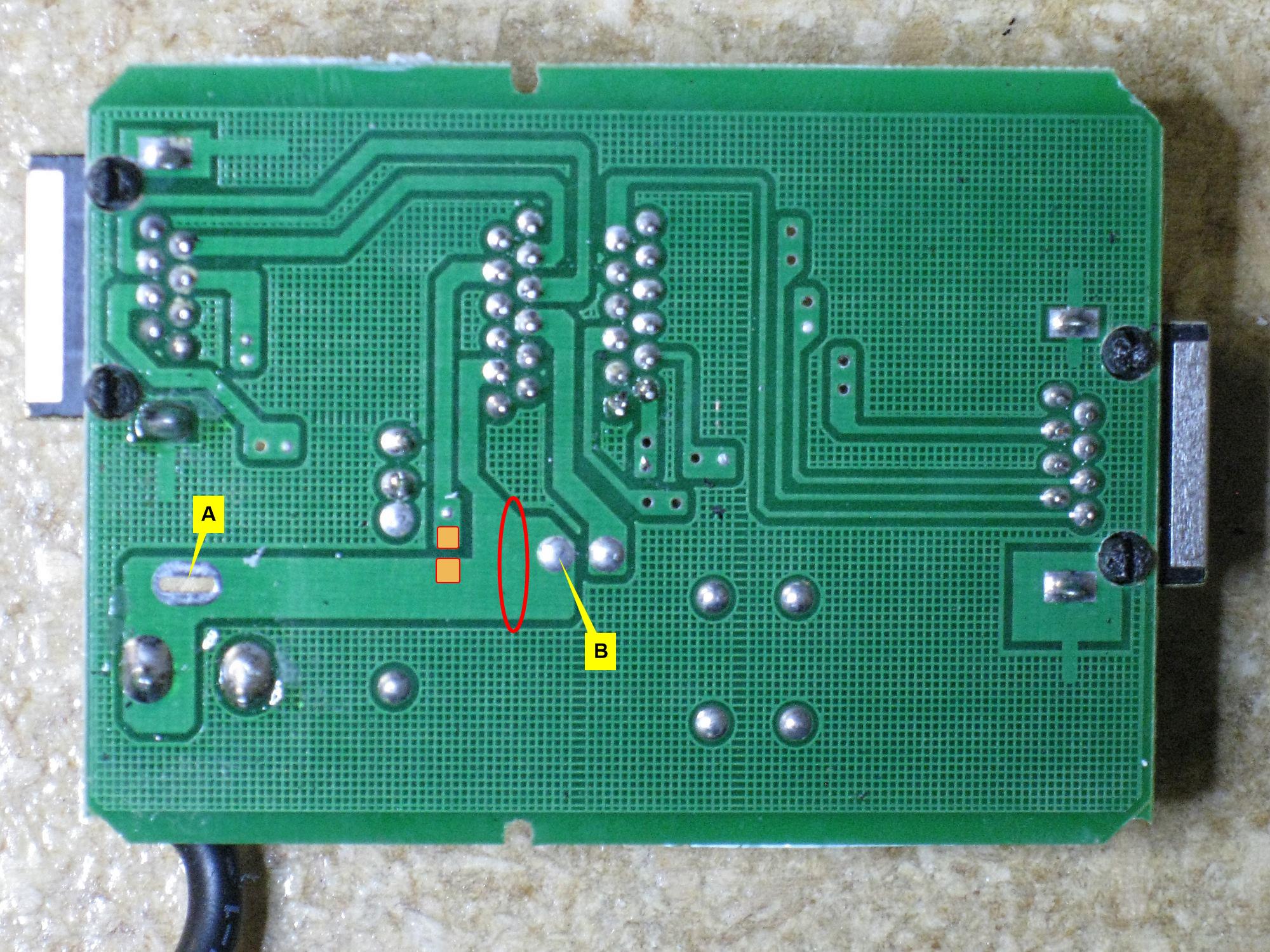
All the other work happens on the other side, so flip the board over.
Cut the trace at the location in the red ellipse. Once again you can check you’ve cut right through with a multimeter on continuity test between points A and B. You also need to scratch off the solder mask in the location highlighted with two copper (ish) coloured squares – DO NOT scratch the trace off, just the mask.
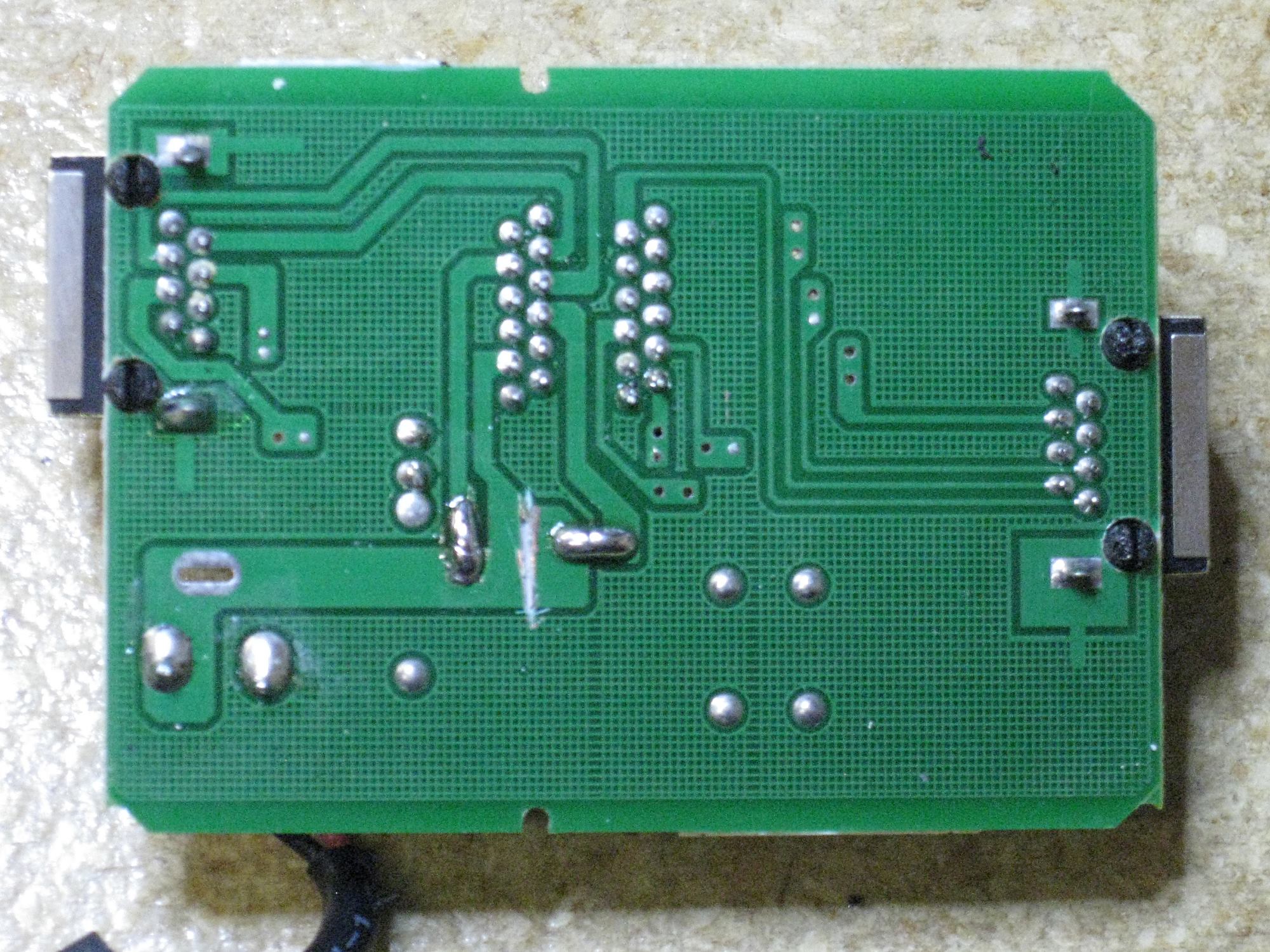
You should now have a board that looks like the next image. The final job is to add two solder bridges as marked by the blue ellipses.
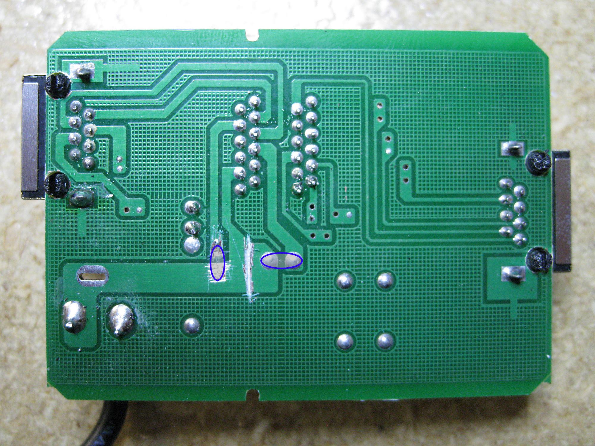
All going well, you’ll have a board that looks like this.
If you plug an ethernet cable into the PoE out socket, you should be able to continuity test all 8 pins go back to the correct DC input wires.
If you were careful opening the case, you should be able to get it back in without too much effort.