Adjusting the float voltage of a Tycon Systems TP-SCPOE-1224
The Tycon Systems TP-SCPOE-1224 is a Solar and Power over Ethernet powered DC UPS.
You connect it up to a 12v battery, power it over ethernet, add an optional solar panel and it will output 24V DC until the supply stops and the battery runs flat.
The units are very reliable, but the battery float voltage seems to sit at around 13.3 volts. This is a little low for AGM batteries which should be kept in the 13.6-13.8 volt range.
I’ve had multiple batteries fail within 16 months after being held at a 13.3v float. I recently decided it was time to see if it was possible to increase the float voltage.
I got in touch with the team at Tycon Systems. After receiving (and not accepting) an initial “Not possible” response, they came through with the goods – A section of the schematic specifying that resistors R45 and R49 control the float voltage. They also advices that the charge voltage increases relative to the float voltage, so just changing the float voltage will increase the charge voltage by a relative amount as well.
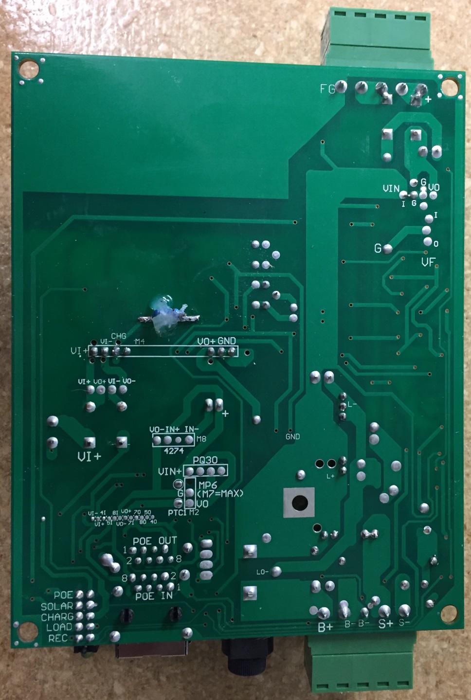
It’s easy to open up the unit. Turn it over, remove the four rubber feet to reveal four screws. Remove these screws and the two halves separate with ease.
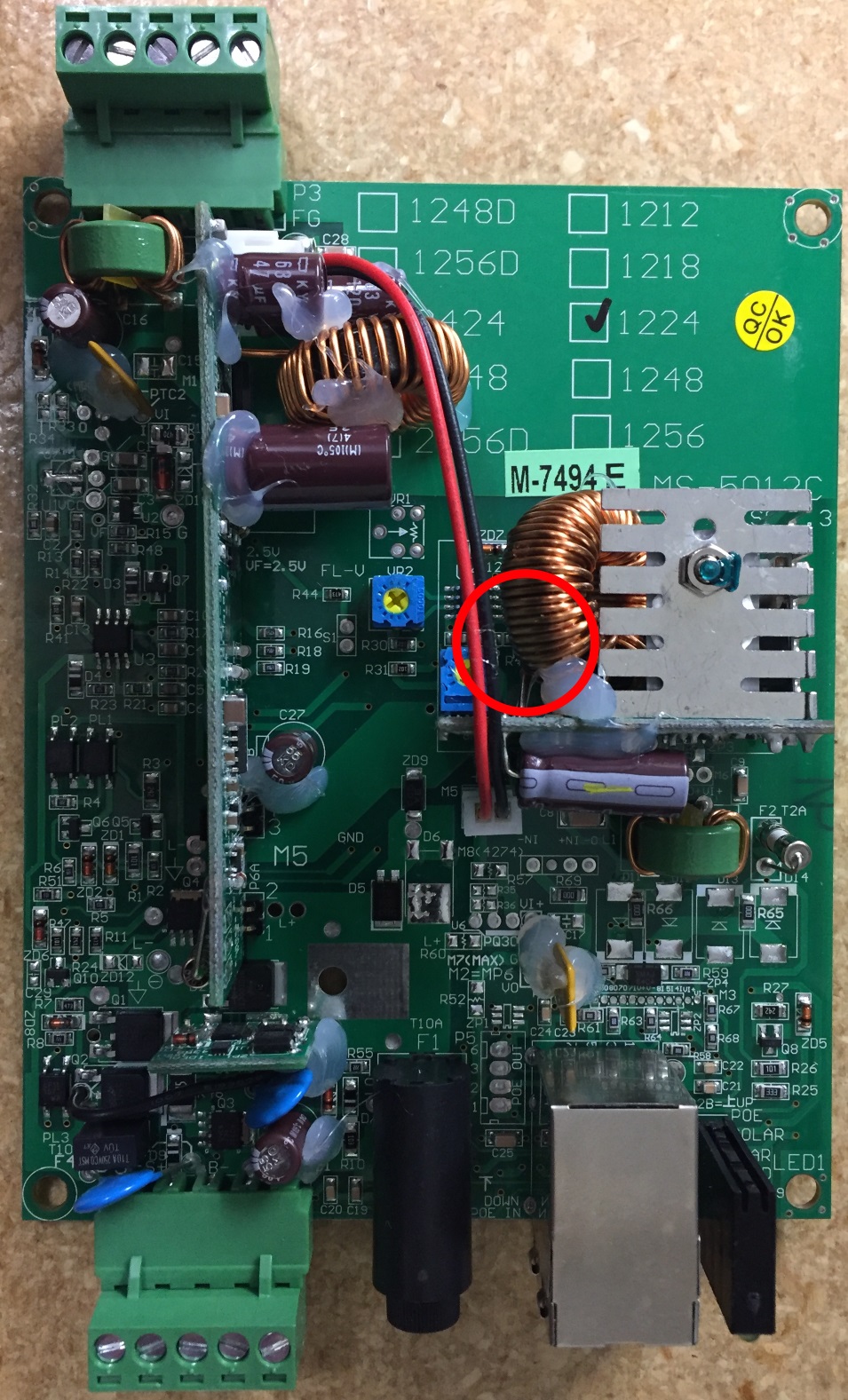
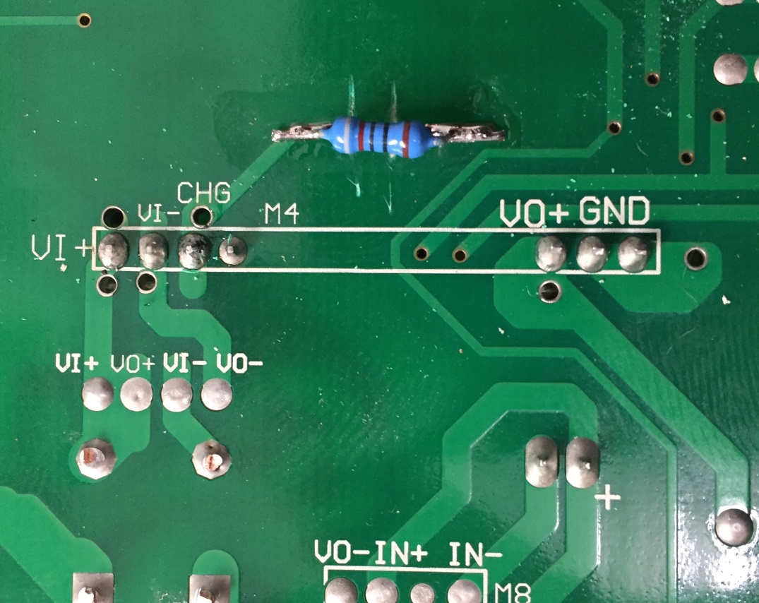
Once you have it apart, you’ll soon find out that resistors R45 and R49 are difficult to access due to their location. Because of this, I decided it was easier to flip the unit over and work on the traces from the other side.
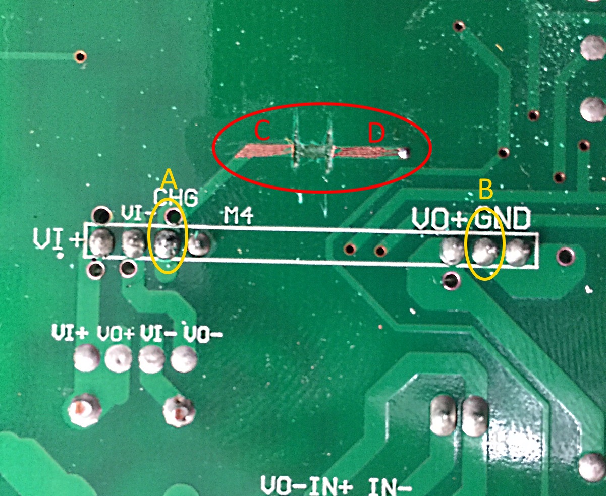
You will need to cut the trace between marked points C and D.
At this point you then have two options, either bridge the freshly cut gap between points C and D to INCREASE the resistance, or levae the track between C and D cut and then add an entirely new value between points A and B. Note that the 18.95K resistance is fitted between points B and D.
If you’re bridging the cut, carefully scratch off the solder mask, apply some flux and tin the trace in preparation for a resistor.
You can immediately test any adjustments with a voltmeter across the BATTery connector – Do not have a battery connected as this may send the unit into a Bulk charge mode rather than the float that we’re trying to measure.
Using a trimmer potentiometer, I got to my target float voltage of 13.8V by adding 665 Ohm between pioints C & D.
I then tested by adding standard/common resistor values:
680ohm = 13.81V
750ohm = 13.84V
820ohm = 13.86V