I’ve previously blogged about CHDK. It is the “Canon Hackers Development Kit” and is alternative firmware for Canon digital cameras. It never actually overwrites the camera firmware and can give a camera many extra features not available in the default firmware.
For radio control applications, specifically aerial photography, there is a real bonus in being able to control a camera to take photos from the radio control unit.
CHDK will allow your camera to take photos when 5volts is supplied on the +ve pin of a USB cable. I’ll be using this feature to show you a simple way of interfacing a channel from your RC gear to the camera.
Here is what you’ll need:
- An old servo – The moving parts are not required so one with a broken motor, bearing or gears is perfect
- A diode – I’m using a bog standard 1N4004 rectifying diode. Anything should do, but I suggest something that can handle at least 3 amps
- A USB cable that you are happy to destroy, or some wire and a USB plug to go into the camera
- Soldering iron, small screwdrivers and heatshrink or insulation tape
First of all, get yourself a servo.
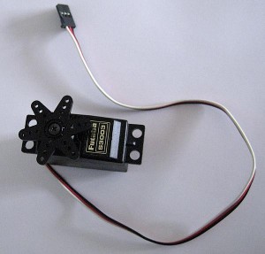
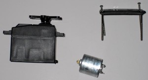
Now take it apart, taking care when removing the circuit board. You should have the servo case and a circuit board with a motor attached.
Desolder the motor and put it to the side.
Take your USB cable, measure from the plug that goes into the camera and cut it at the length you need (around 30cm should be find for most applications). Strip the red and black wires. You won’t need the other wires, so cut them off if you want.
Now, you want to solder the black wire to one of the pads on the pcb where the motor was soldered to. Solder the black to either of these pads – There is no back to front an it can be reversed on the transmitter with servo reverse.
On the other pcb pad (which the motor was soldered to), solder the diode. The diode should be soldered so that the end without the stripe goes to the circuit board. The other end of the diode (with the stripe) should be soldered to the red wire from the USB cable.
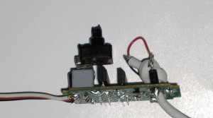
Now, turn the potentiometer on the circuit board to approximately the centre position. You can now plug the modified servo into your receiver and turn it all on.
If you put a multimeter across the red and black wires of the USB cable, depending on the position of the transmitter stick, you’ll see around 4.8 volts. The diode simply stops the voltage reversing when the servo wants to go in reverse.
Turning the potentiometer will alter the central position where the servo sends the 5 volts to the USB cable.
You can either replace the potentiometer with two fixed value resistors, or simply put a dollop of glue on it to make it stay in the correct position.
I’ve got mine hooked up to channel 5 (landing gear) and in one switch position, the unit outputs 5 volts, in the other 0 volts.
Now, here are some scripts for the camera.
This script is made for continuous shooting, when your camera is set to multiple shot mode. It will focus when triggered by the USB cable. It will continue taking photos without re-focusing while the USB trigger is turned on. The blue LED will flash as a “heartbeat” so you know the script is running.
This script is excellent for taking aerial maps at approximately the same height as it will allow you to take around 2 images per second (if flash is disabled), but remember the focus and exposure is set from the first image. Note that the USB port needs to be “held on” even if only one image is to be taken.
@title ContinuousShot

a = 1
print "Continuous Shot"
while 1
  wait_click 1
  if is_key "remote" then press "shoot_full" else release "shoot_full"
  gosub "flashLED"
wend

:flashLED
  if a=1 then a=0 else a=1
  set_led 8 a
return

end
This script is made for single shot shooting. Whenever the USB cable is triggered, it will focus and take one photo. If the USB trigger is still enabled once the photo is taken, it will take another (and focus again). If you choose to leave the USB triggered, it will take photos over and over again, but a lot slower than the continuous mode script.
Note also that this script only requires the USB trigger to be enabled for a split second for it to take the entire photo.
The blue LED will also flash as a “heartbeat” so you know the script is running.
@title SingleShot

a = 1
print "single shot"
while 1
  wait_click 1
  if is_key "remote" then shoot
  gosub "flashLED"
wend

:flashLED
  if a=1 then a=0 else a=1
  set_led 8 a
return

end
